Backpacking Drone
Personal Project
Backpacking Drone
I have been interested in drones for a few years now and have owned a few toy drones myself. I have always wanted to do aerial photography, but have found that the cost of these drones was quite high. With the open source community now serving all the capabilities I was looking for- autonomous flight, altitude hold, return to launch, and telemetry - I decided to start on my own. I began with a kit from Aliexpress which seemed to have all the basic pieces for a good price. I have since learned how to optimize the build for the lowest price possible, and have decided to build my drone from "scratch" seeing as how I have many of the tools I need at my disposal at school.
Click Here to go straight to the build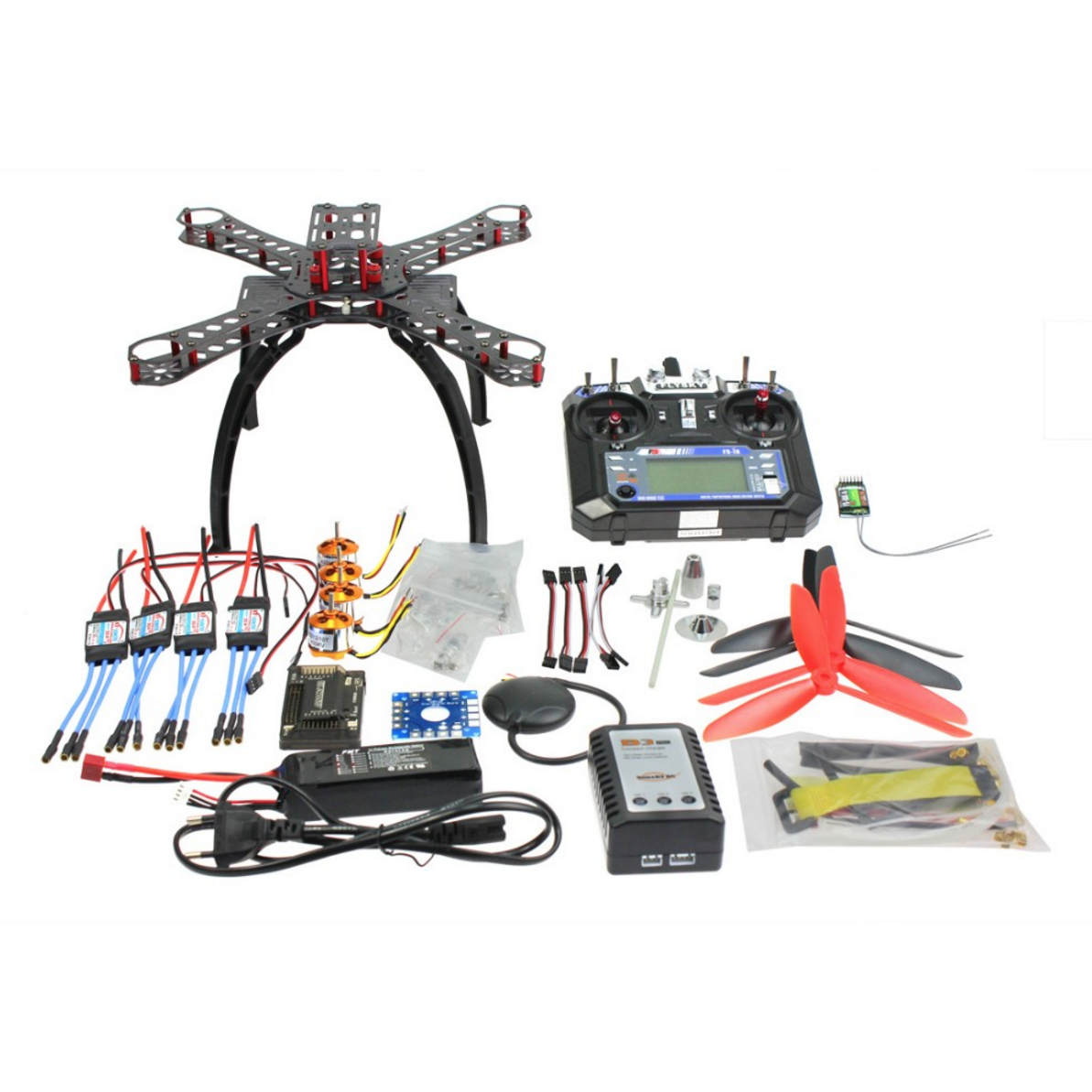
The Kit
- 1 "Carbon Fiber Alien Across Mini Frame"-320mm(Estimated)
- 4 Presumably A2212 XXD 1400KV motors
- 2 CW, CCW 7045 3 Blade propellers
- 4 XT-Xinte 30a ESCs
- 1 Cloned 2.8 APM controller with built in compass
- 1 6m GPS with L5883 Cable
- 5 Servo Lead Extensions Male to Male
- 1 Power Distribution Board
- 1 Folding Antenna Mount
- 1 Flysky FS-i6 6CH 2.4G AFHDS 2A LCD Transmitter
- 1 Flysky iA6 receiver
- 1 2200 Mah Lipo Battery, 20C
- 1 IMAX B3 Pro compact Balance charger
- 1 American plug adapter
- 1 Tool Kit (Some zip ties, a battery strap, and an action camera strap
Unfortunately the price has changed from its original $165 price. The kit was not a bad price for having everything it had. Looking back, I could have saved an additional $20 by purchasing everything separately and possibly more by foregoing a kit with a frame to use household materials instead. Only with more experience have I been able to get a better sense of prices in this hobby, and I continue to improve my deal finding.
What I learned from buying a "RTF" kit
I spent a couple weeks watching hours and hours of video online to prepare me for my venture into DIY multirotors. My best resource for this was Andy RC's channel. Specifically, how to build a cheap quadcopter. Andy is full of knowledge and not afraid to explain things mundane to those with more experience. I also recommend the channel Painless 360, especially for those looking to set up their APM. Lastly, I recommend Oscar Liang's website for written tutorials and even more in depth info. Despite these channels being great resources, I still managed to have quite a difficult time setting up the quad as even the greatest amount of detail in these videos does not tell you everything to know.
For example, my "RTF" kit came without a power module, something critical to supplying power to the flight controller. Had the videos covered this piece, I may have purchased a different kit which might have included it. I also did not understand that in order to do autonomous flight, one needed the telemetry package unless they are comfortable with being unable to change the route once in the air. It took resources such as Oscar Liang's blog to explain these more clearly, in addition to more issues such as why I should change my ESCs from BEC to OPTO. All in all, I recommend doing something like this with the guidance of someone who has experience in building drones, DIY or not. These resources have been my best for learning how to improve my design.
Seeing as how the frame was not optimized for my use case, I decided the included frame in the kit would simply be a base for me to get comfortable with building multirotors. However, this plan too ended up being corrupted by time constraints.
The Upgrades
For the original kit
- Power Module with T type connector (5v to flight controller)
- 2 Axis Gimbal (I would have gone for the 3 axis except to save for costs, and I was originally intending to use the stabilized camera for FPV also, and would not be able to adjust the yaw with the necessary attached cables.)
- Servo Lead Extensions (Used to connect to the Tx from the Sj4000 clone)
- JST connectors(These were used to power the Tx and Gimbal from the PDB as each came with these connections)
- Eachine 600mw TS835 Tx(This one produces 5v to power the Sj4000 unlike the TS832)
- 433MHz telemetry kit (I had read that it may receive less interference in the areas I would be travelling to)
- FX 4.3in 32ch Receiver (The cheapest all in one FPV monitor I could find. I figured the smaller screen size in comparison to the 7" standard could help keep the size of everything down.)
- 10 Pairs CW, CCW 7045 3 blade propellers
Many of these items can be found cheaper on Aliexpress or Ebay. Some of the choices of where to purchase from were made by prioritizing shipping speed, necessitating that the sender be from the contiguous states.
Custom Build Frame Pieces
- 2 16mm diameter carbon fiber tubes, 500mm
- 16 16mm brackets
- 4 Tarot Position holders
- Carbon Fiber Motor Mount Plates
Additional Pieces(Owned before the start)
- Sj4000 Clone(For FPV, Must have TV Out)
- Eken H3 (For use on Gimbal)
The Custom Build
As mentioned above, it was understood that the frame that came in the kit would not be useful for me while backpacking. The reason for this is that it does not easily pack down in size as every piece is rigid and many of them protrude quite a bit, something that does not lend itself well to packing. While I knew that I would not be using this frame during my trip, I had not yet determined that I would be building my own frame. Determining this resulted from me researching all options available. The methodology for determining which frames were best was by size relative to footprint, with a maximum footprint of no larger than a foot in any dimension. I figured this could be the maximum size I could fit in any bag or backpack, though I am sure even this length could be beyond the capacity of many bags. The reason for preferring a larger size to a smaller size was the ability to expand the drone for future capabilities as smaller drones have less lift and can carry less modules.
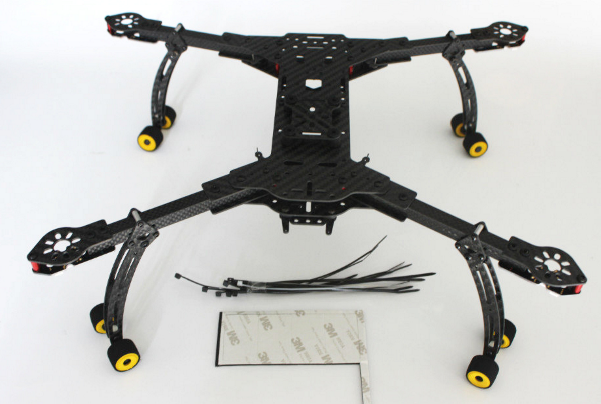
The DH410 Frame $106, 222g
This thing is nearly perfect. What makes it so special is that the entire frame folds down to 330mmx160mmx60mm with 10 inch blades. Even the landing gear folds onto the arms. The price is slightly expensive, but considering the time it takes to model and the cost of materials, this frame is not a bad deal. A 410mm base allows for a quad with up to 3kg of thrust with the right motors, meaning more expandability.

ImmersionRC XuGong V2 Pro $169.15 ($143.65 If you wait for Hobbyking to offer you a popup discount), 96g
The Xugong V2 Pro is light and small. It folds in a way very different from the DH410 and has a different profile. This holds the stabilized camera on the front as opposed to below the frame. The folded dimensions are 240mmx300mmx140mm, making its footprint slightly larger, which makes sense considering it is a 460mm frame. The build quality is sound using anodized aluminum and carbon fiber. The negatives I can see are the lack of landing gear, price, and the fact that the arms can not fold slightly further.
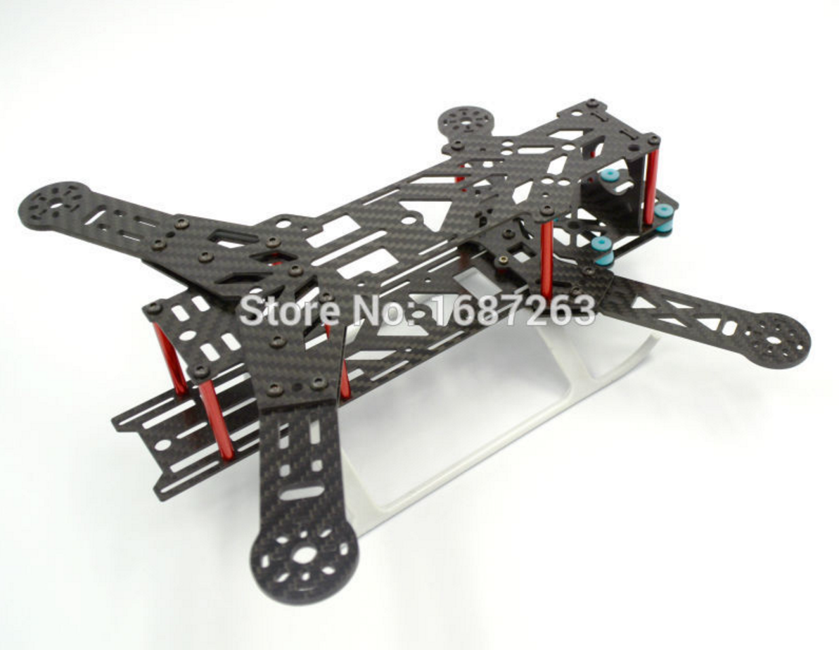
BX300 Folding Frame $26.88 (Seen as many other names online), 154g
This frame is even smaller than the one that came to me in the kit; however, I wanted to be very open minded about the size quad I could use. While I typically always want to go bigger, the nature of a backpacking drone is one that prefers smaller. Just how small one could go with a traditional store-bought gimbal was my main question and here is the answer. As such, a 300mm quad can fully get the job done, but it may limit battery size and the amount of other components one can mount on the quad due to size and weight restrictions. Because I want to do autonomous flight and want to be able to travel longer distances, I favor a frame that can allow me to carry a bigger battery. Additionally, the clearance below the aircraft is not large enough for a gimbal. While the video above shows that one can mount a gimbal above a multirotor, I have opted not to do so in order to clear the shot of propellers.

HobbyKing Alien 560 Frame $73.04 ($67.82 if you wait), 520g
This frame is very similar to the DH410 in design. It is of larger size, meaning it can carry fairly heavy equipment. The folded size is listed at 240mmx300mmx200mm.
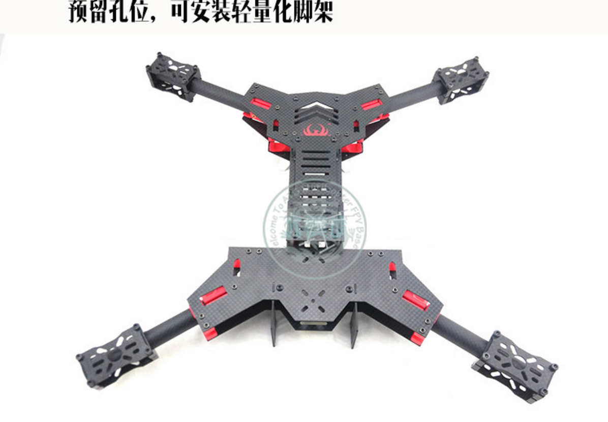
HF450 Alien $119, 376g
This is simply another option to throw into the mix. One of the benefits of this frame is that it comes ready for X8 configuration. It also appears to be very robust compared to some of the other designs. I was unable to find information as to its size when folded.
Back to the Build
After looking at all the options I determined the best frame for me was the DH410. However, I did not want to spend the money and instead opted to design my own frame. Using the DH410 as a reference as well as the Mokaframe. I found that the DH410 had the compact form I wanted while the design elements of the Mokaframe made for an extremely easy and cheap build. The mokaframe at a glance makes me question why anyone would want to buy any sort of frame except for the fact that not everyone has access to a laser cutter and modeling software.
I recommend purchasing the same pieces I did on Aliexpress to save cost, but seeing as how time is winding down for me to get enough experience flying my quad before my trip, I opted for Amazon and domestic Ebay prices to expedite the process.
Initial Designs
The Arm Position Holder
These pieces ultimately ended up being purchased rather than made. I believe they can and should be made by any true DIYer, but I purchased these before having experience with inlaying threaded mounts into my 3d printed piece. I imagine they are not too difficult to get right except for the piece requires just enough give to slide the 16mm arm through the smaller opening. I imagine there are some filaments available with these qualities.
Motor Mount Bracket
These can certainly be made with a 3d printer. I opted for purchasing aluminum CNCed versions for looks and rigidity.
Motor Mount
I modeled these in hopes of using the available acrylic at my school for the mounts. Unfortunately, the thickness of the acrylic made it unsuitable for use with the screws I was using for the motor mounts as there was less than twice the thickness of the acrylic left in the length of the screw, not enough to twist a nut on.
Original Frame Base
This has since gone through at least 6 revisions for adding new precut holes and optimizing space efficiency. This design was not fit to fold correctly and did not have prefabricated spots for additional support.
Original Arm Design
I have not fully built up the design but expect to keep to this look.
Model, Cut, Fit, And Model Again
After making this initial rendering I felt pretty confident that I would be able to make something of quality given the resources I had and the materials I picked. Looking at the various designs online only proved that most frames are designed to be incredibly simple with common parts with a few exceptions. For hobbyists, making a frame is something easily done, but as the size and needs of the frame increase it can be expected that some of these stock parts may not suffice.
My design was not overly complex, but it became clear that some aspects of it would need to be changed as I tested the structural integrity of the materials with each revision. The initial renderings seen above did not include the pivoting arms required of a folding frame, and here is where much of my focus had to turn.
I modeled this initial rendering after the Mokaframe which used the arm brackets as the pivot fitting. I believe this model could have worked for me, except for the fact that I was using acrylic as the base material rather than carbon fiber. Carbon fiber is much stronger than acrylic and does not easily flex or track. Additionally the specific acrylic I was using was 1/8" thick, while the screws for the arm bracket CNCed halves left barely 1/4" of thread left to pass through both sides of acrylic.
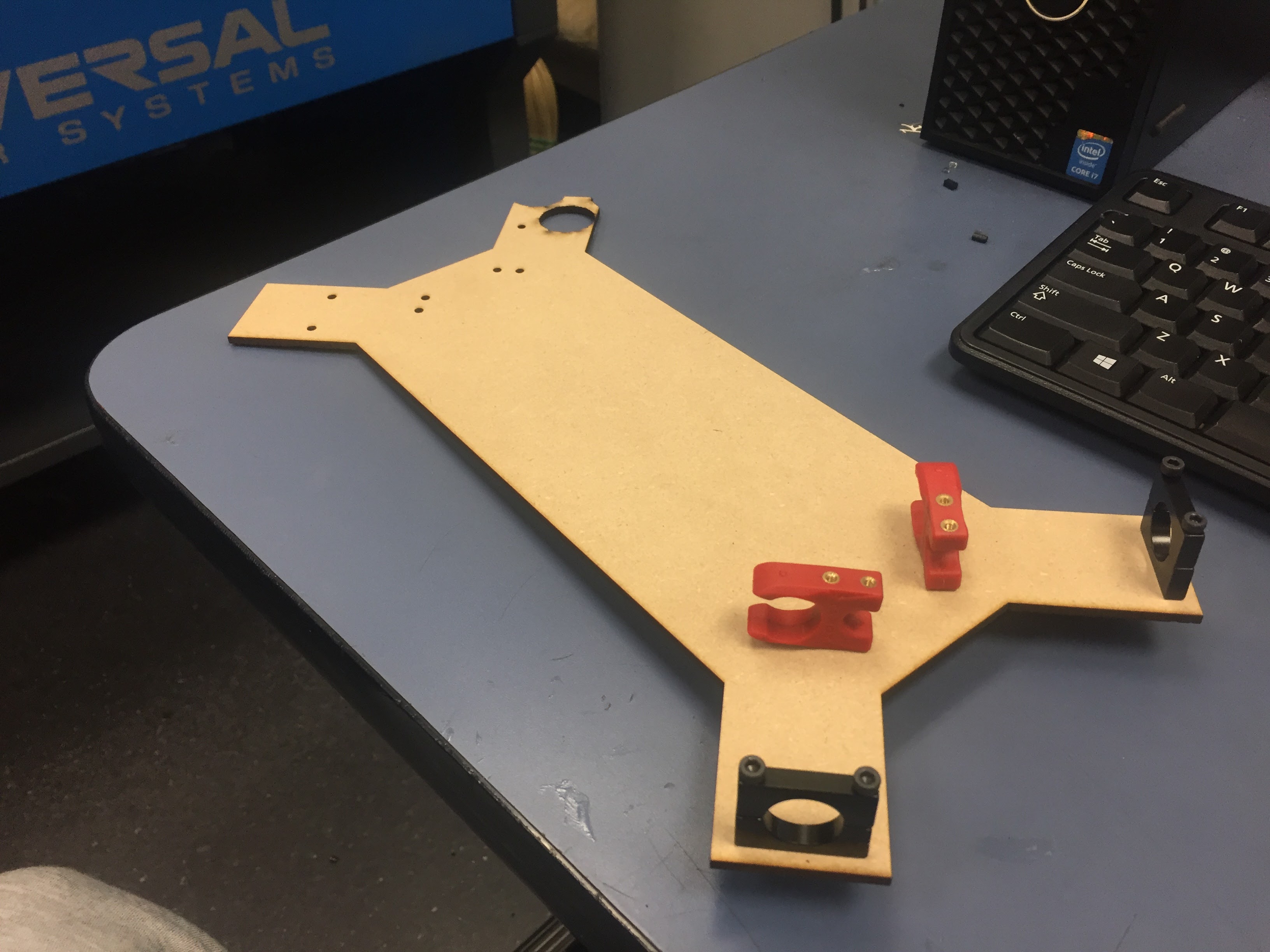
Here the position holders and arm brackets are mounted onto the very first laser cut acrylic base. As you can see, there is not much thread left on the screwSs of the arm brackets.
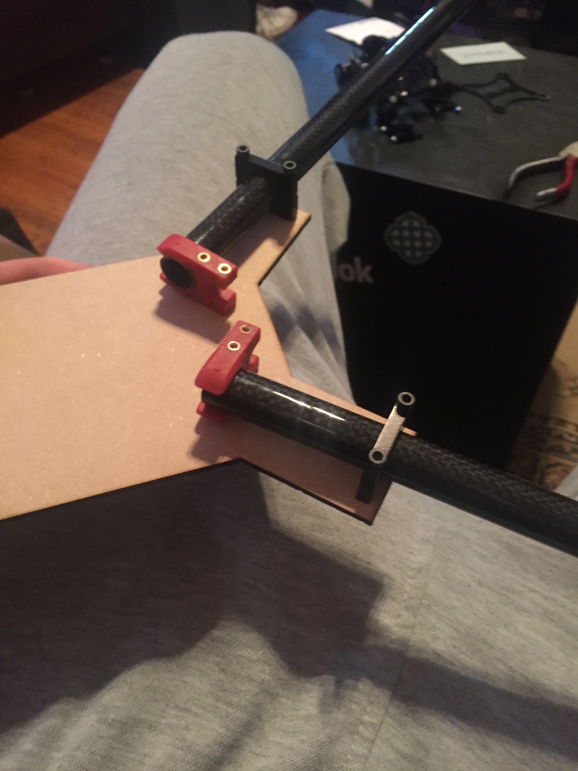
Another angle, you can see how I had not yet incorporated the track for the arm bracket to pivot. I also mounted the position holder in the opposite direction.
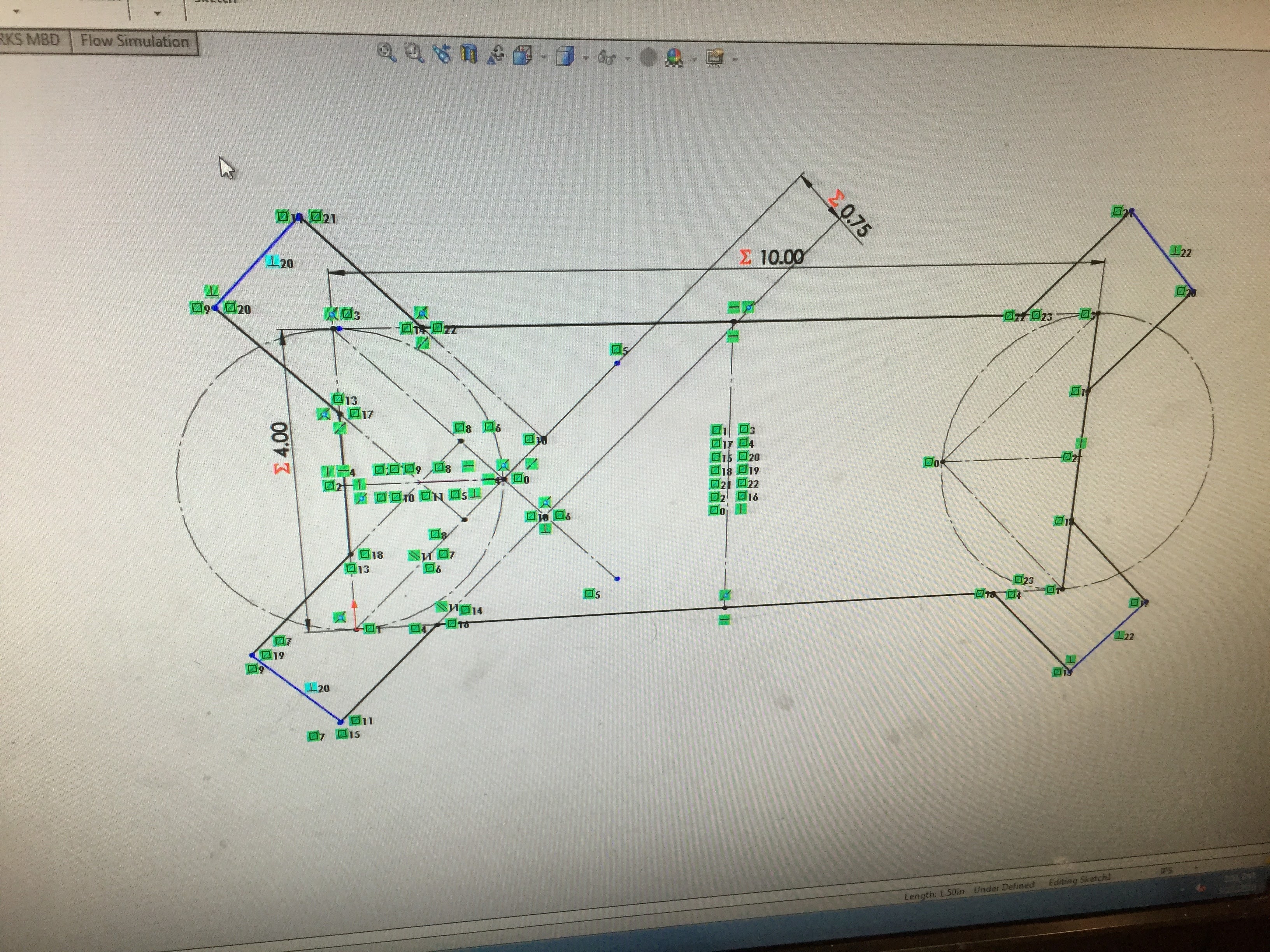
Here is simply a picture of the modeling process. Below is a picture of the rendering in carbon fiber. At this point, I had believed I could cut carbon fiber sheet in the laser cutter and was using acrylic as a cheap material for fit.
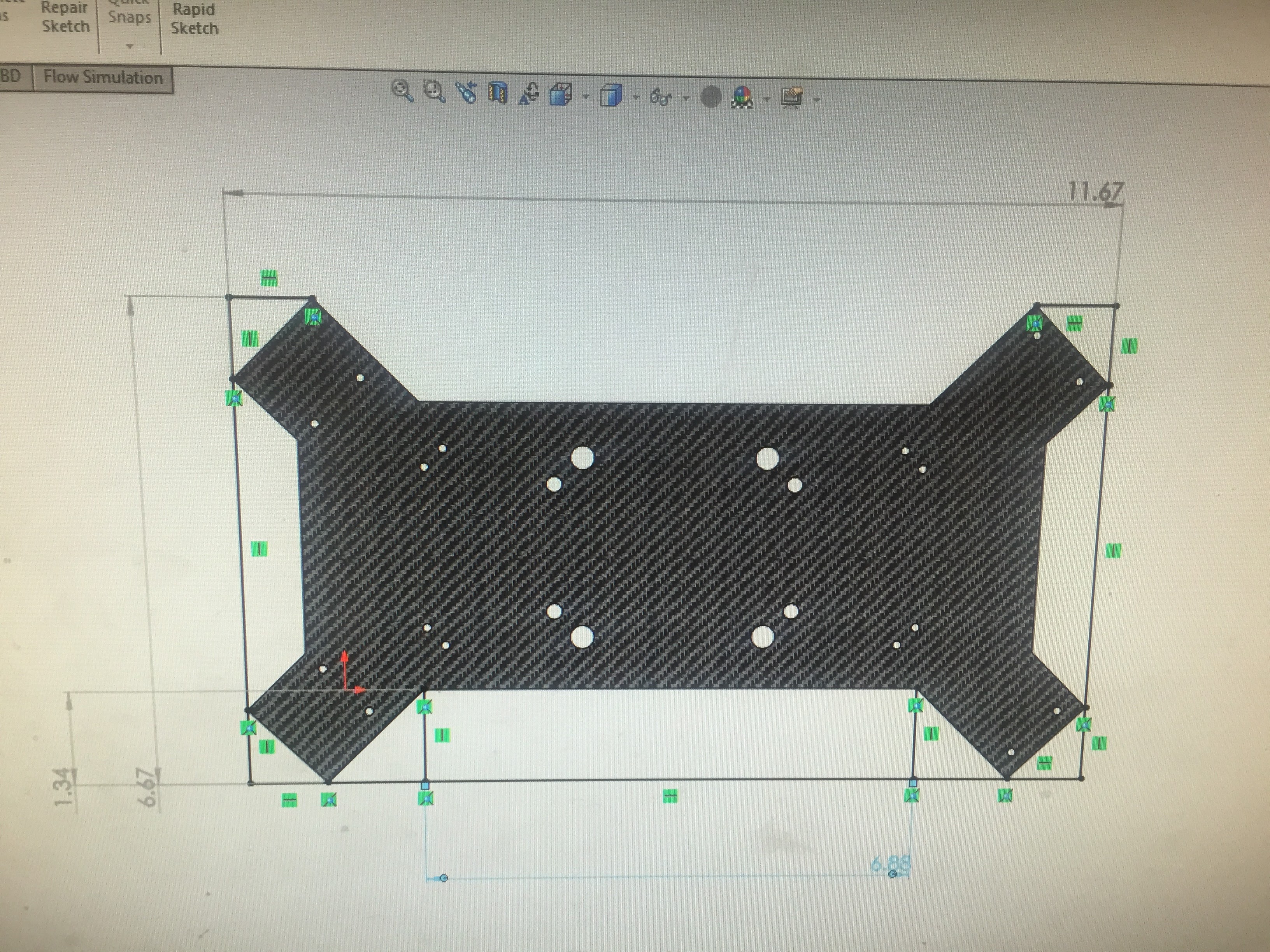
Revision 2, adding the holes from the APM vibration mount and gimbal.
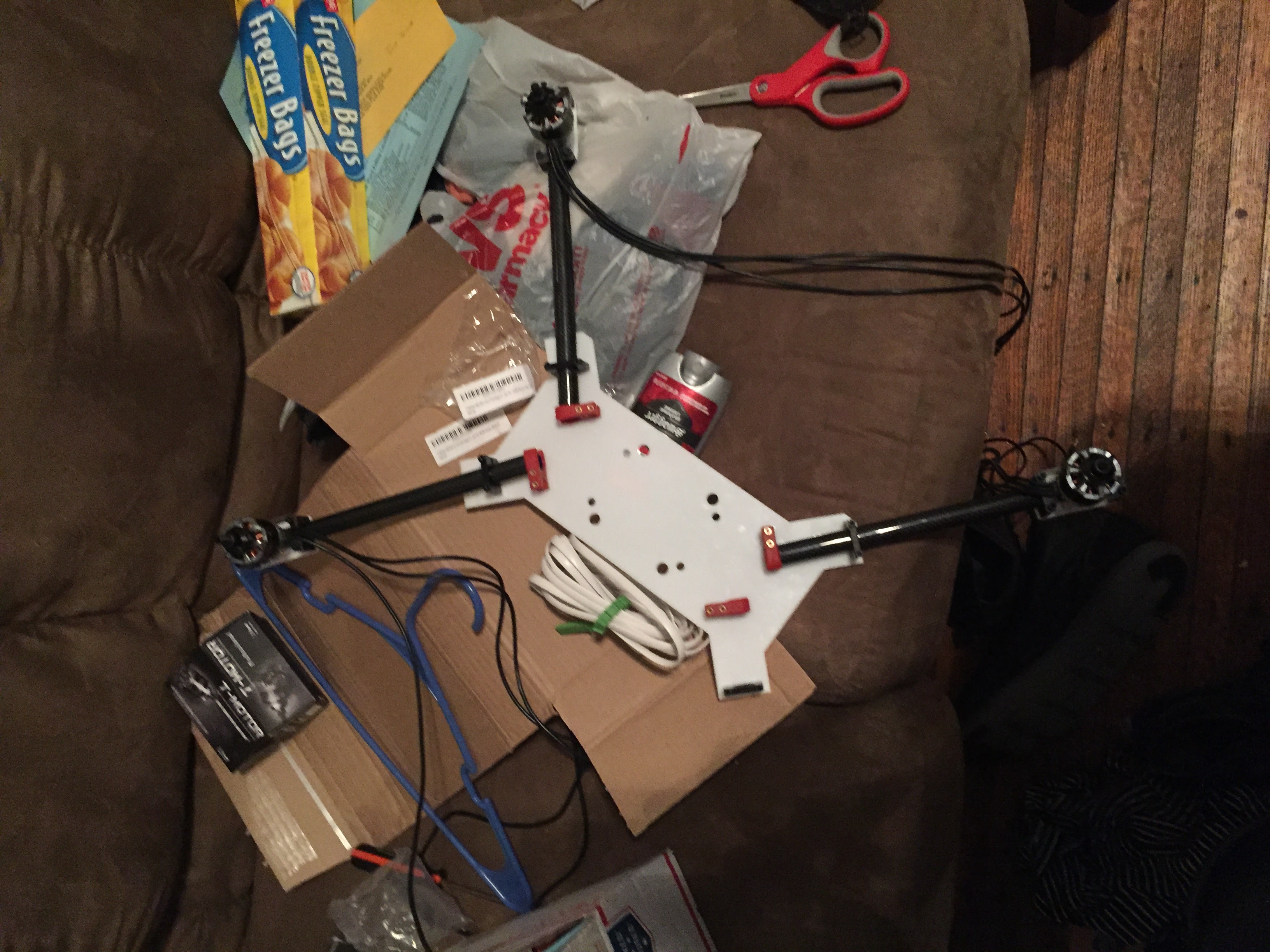
The life of a college student doing too much. Motors came in, testing for fit. Here, I was carefully observing the amount of flex present from the weight of the arms.
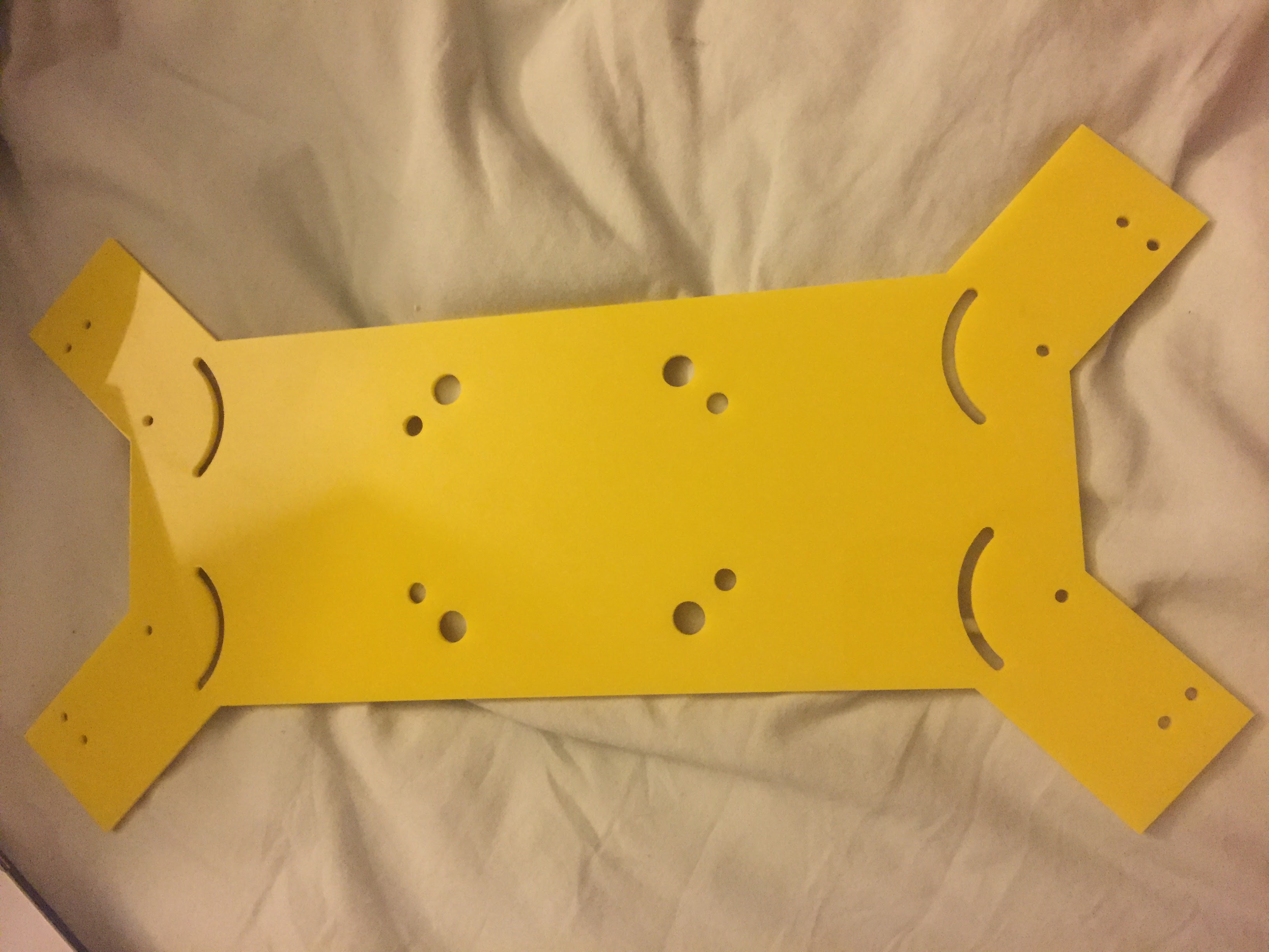
Here is the fourth version of the base. Every night after modeling my pieces I would sleep thinking of how to improve the design. At this point, I was quite literally dreaming in CAD, and found I could efficiently model the pieces from last nights sleep in minutes, having already created them in my head. Here, the arced pieces are where the arm brackets unfixed screw would be allowed to glide across the surface. I also switched the locations of the position holders and arm brackets. previously the brackets position holders were more centrally located, but I moved them after learning from my third revision that having the arced sections outside compromised the rigidity of the frame.
Necessary Changes and A New End Goal
At this point I was working simultaneously on a 360 degree camera also featured on my site. Things were farther along than the quadcopter, as there were less moving parts. My fascination with the capabilities of this technology led me to want to blend the two, which a matter of months ago was extremely novel, yet now I see many moving in the same direction. I had picked motors that could easily handle the extra added weight of the 360 camera, so little needed to change. I had purchased 500mm carbon fiber tubes that I planned on cutting. From here on, I needed to rethink the size of the craft I was building, as I needed to swing larger propellers than originally expected. Now, it was even more necessary to design the folding frame as I still wanted to bring this quadcopter on my Asia trip, but knew I couldn't fit something with rigid arms in a bag. The size at this point changed from my original goal of less than a foot in any dimension, yet i was happy with the new direction of the build.
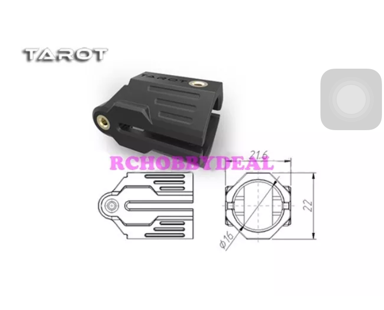
In regards to the realization I had about my design, it became clear that the arm brackets were not the versatile tool I expected them to be. In the Mokaframe, they were used to hold the motor mounts and connect the arms to the frame, all while serving as the pivot point. They worked well because the frame was small and carbon fiber; there simply was not as much stress in 75mm arms in comparison to my 250mm arms. One screw could handle the load. Additionally, I still was dealing with not having long enough screws to go through two layers of acrylic. Longer screws were not easily found online, and I thought I could surmount this problem by lightly drilling into the acrylic to allow the nut to grip the thread. Luckily, at this point I found the part I needed to fix this, which unsurprisingly was also built by Tarot(which makes the position holders).
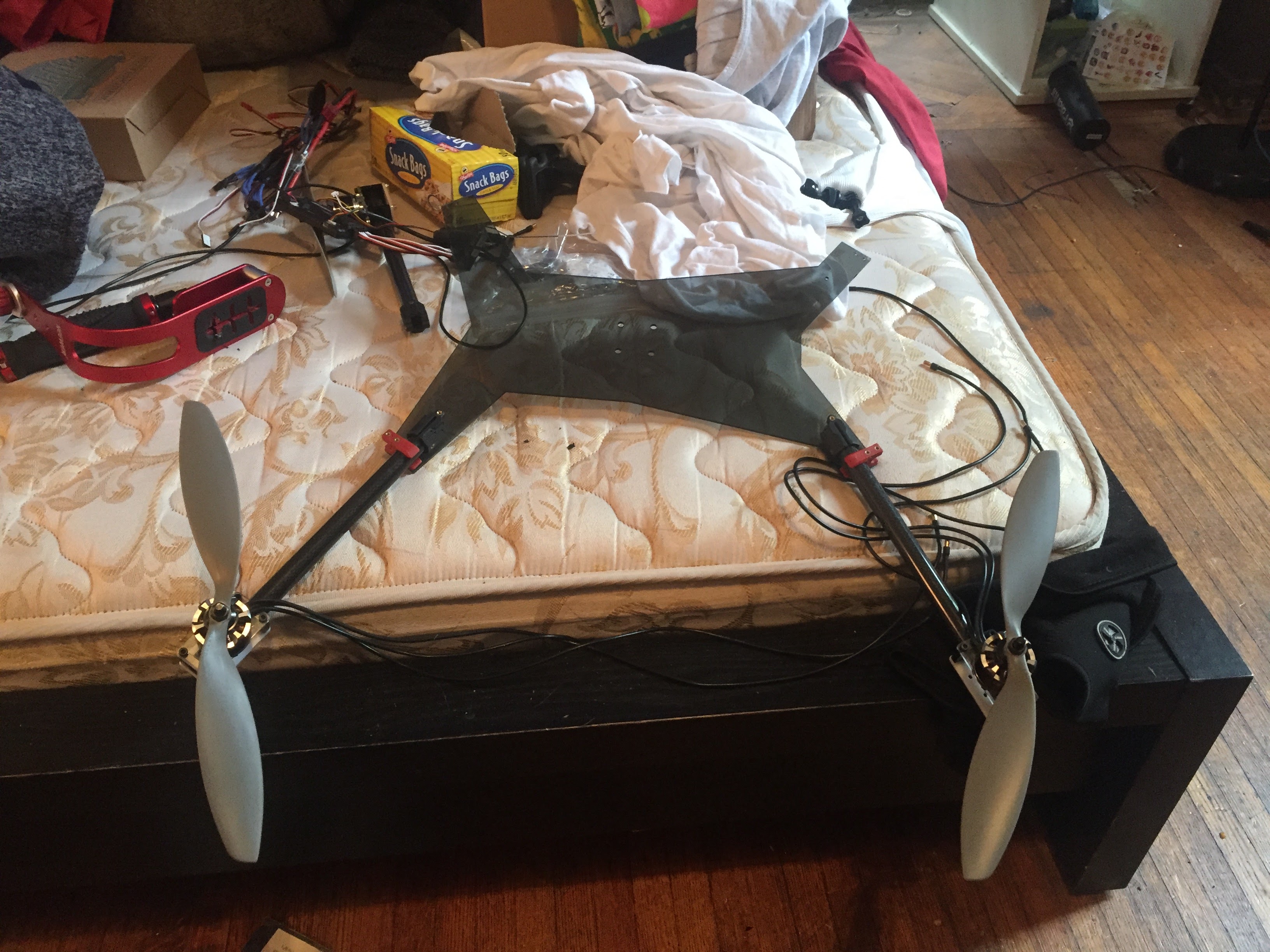
Progression Towards the Final Product
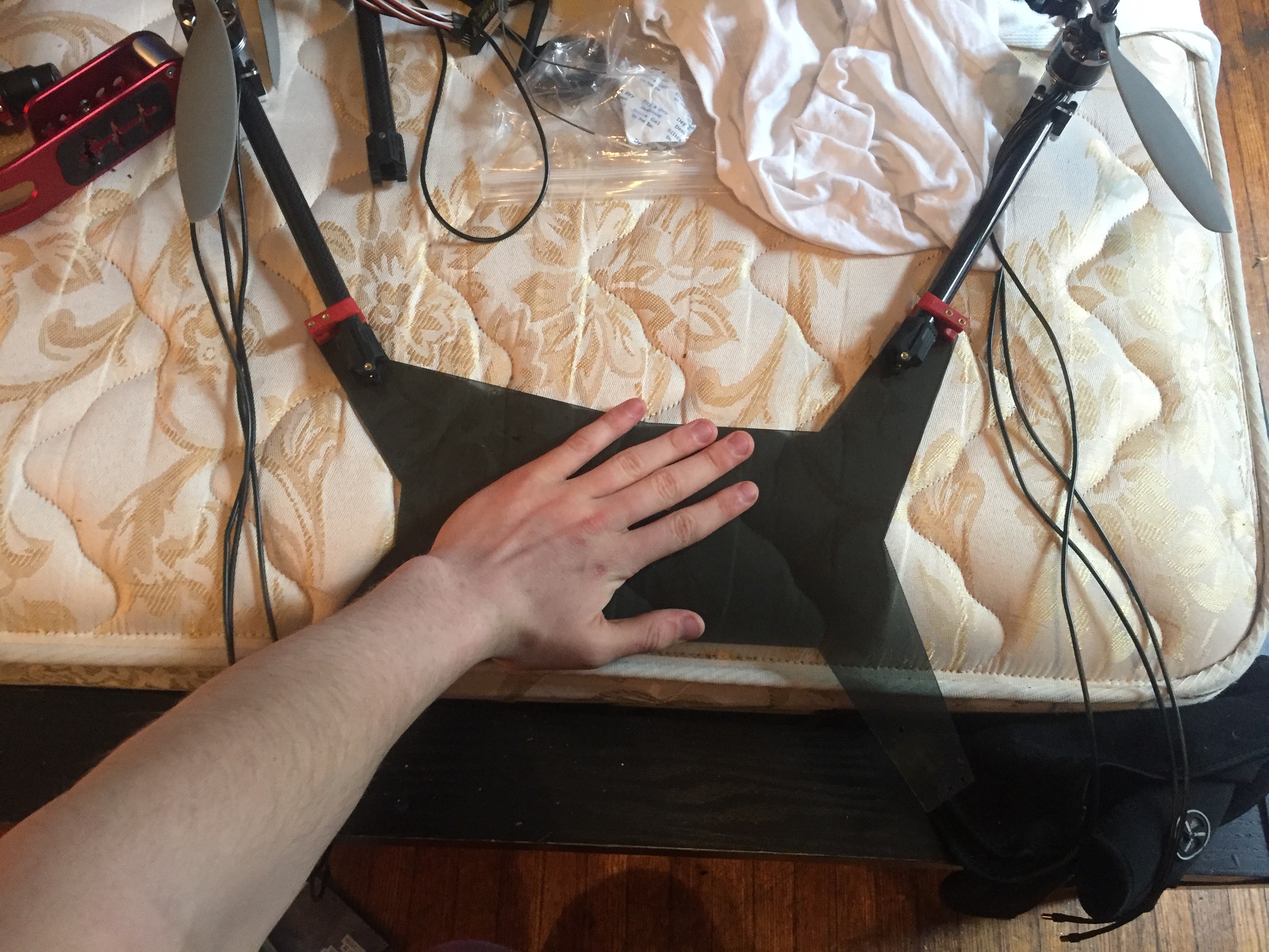
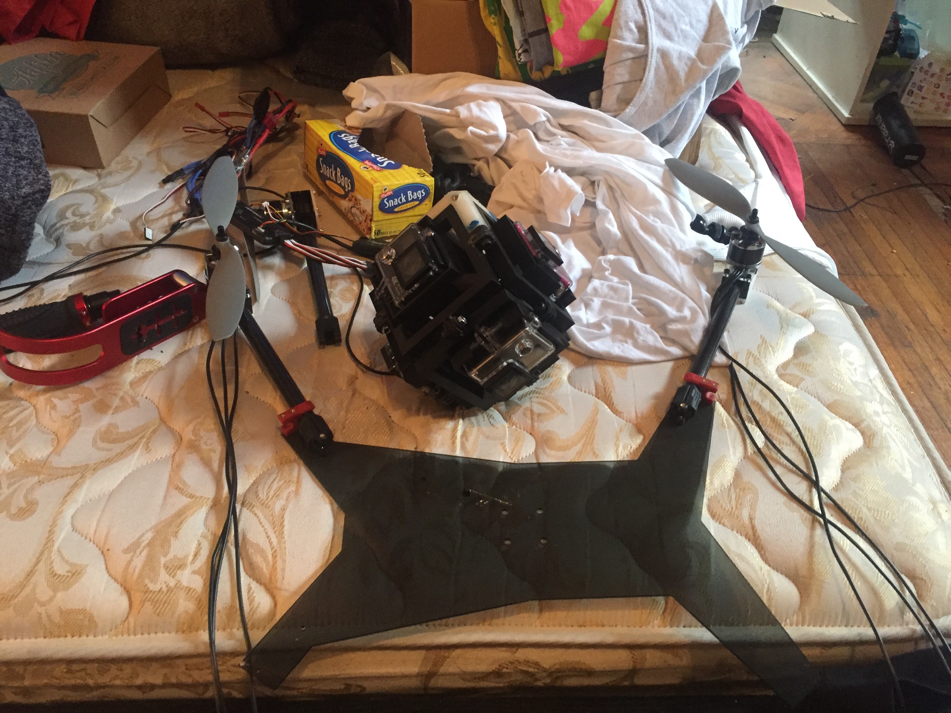
Design Notes
Something I did not do in the first design was fully think through position of the arms fully folded. The actual modeling of this piece was fairly complex in its geometry. It started with ensuring that the length of the model fit the arms, which I left to 250mm in hopes of added stability. I made sure this length was long enough, but as small as possible to limit footprint. I left the rest of the design fully parametric which I will outline here. The equations for the design used the following:
- The 4 holes for the 360 camera mount must remain exactly in the center of all motor mounts.
- The folded arms must be flush against each other and the frame(Limit Footprint)
- This involved making the pivot hole the width of half the motor mount away in latitude from the other.
- The motor mounts had to be equidistant from each other to maintain an X formation
- This involved making the angle of the each arm programmatic.
- The holes for the position holder must be far enough away from the pivoting Tarot piece in order to prevent a colision
- The position holder holes must be far enough away from the angle of the arm in its flying position as to hold it in the correct position.
While not included in this revision, I later had to add a few more design elements that were not parametric before finishing the base.
- A motor mount cutout
- Holes for APM vibration mount
- Holes for gimbal mount
One Last Revision
As noted earlier, acrylic was not the best material to model this in. While I wanted to make this is carbon fiber, I found that there would be many difficulties in doing so. For one, Carbon Fiber is expensive. The longest dimension of the frame was just over 15 inches, which meant the standard 300mm or square foot sheets would not quite cut it. Larger pieces of carbon fiber are much more expensive and would likely mean I would have to buy a piece much larger than I needed unless I were to get the entire design cut specifically for me. In calculating these costs I found it would cost over $200 to do so, and I had not even gotten the frame in the air. It simply was not gonna work. Luckily, I found that acrylic maybe could do the job, with a little support. A revision to add some acrylic supports and I had a rock solid frame.
While not pictured, I also conceptualized a method for reducing the footprint of the quad even further. Considering that I wanted to fly the 360 camera in unison with the gimbal, I wanted an easy way to put on and remove the gimbal for size reduction and safe keeping. I ended up designing "gimbal tabs" which allowed the gimbal to slide on and off the quad when attached to an acrylic mount. The mount was square with the same dimensions to fit the dampeners within. Doing so allowed the gimbal to be safely stored in a box and then quickly slid on for filming on a whim.
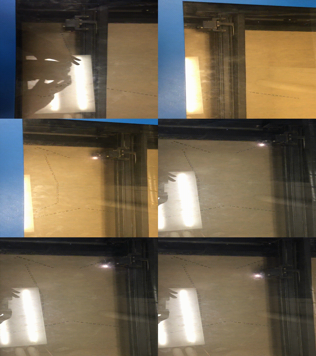
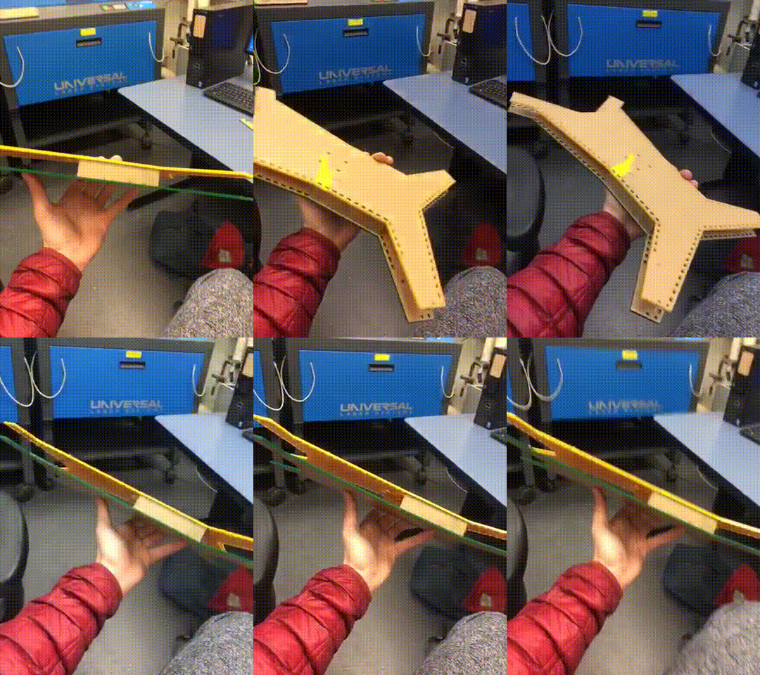
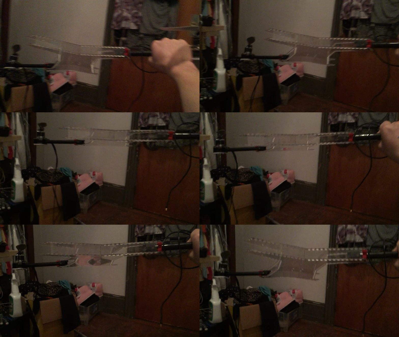
NO FLEX NO FLEX NO FLEX NO FLEX
I did it. Cue final pictures and mockup
Potential Directions
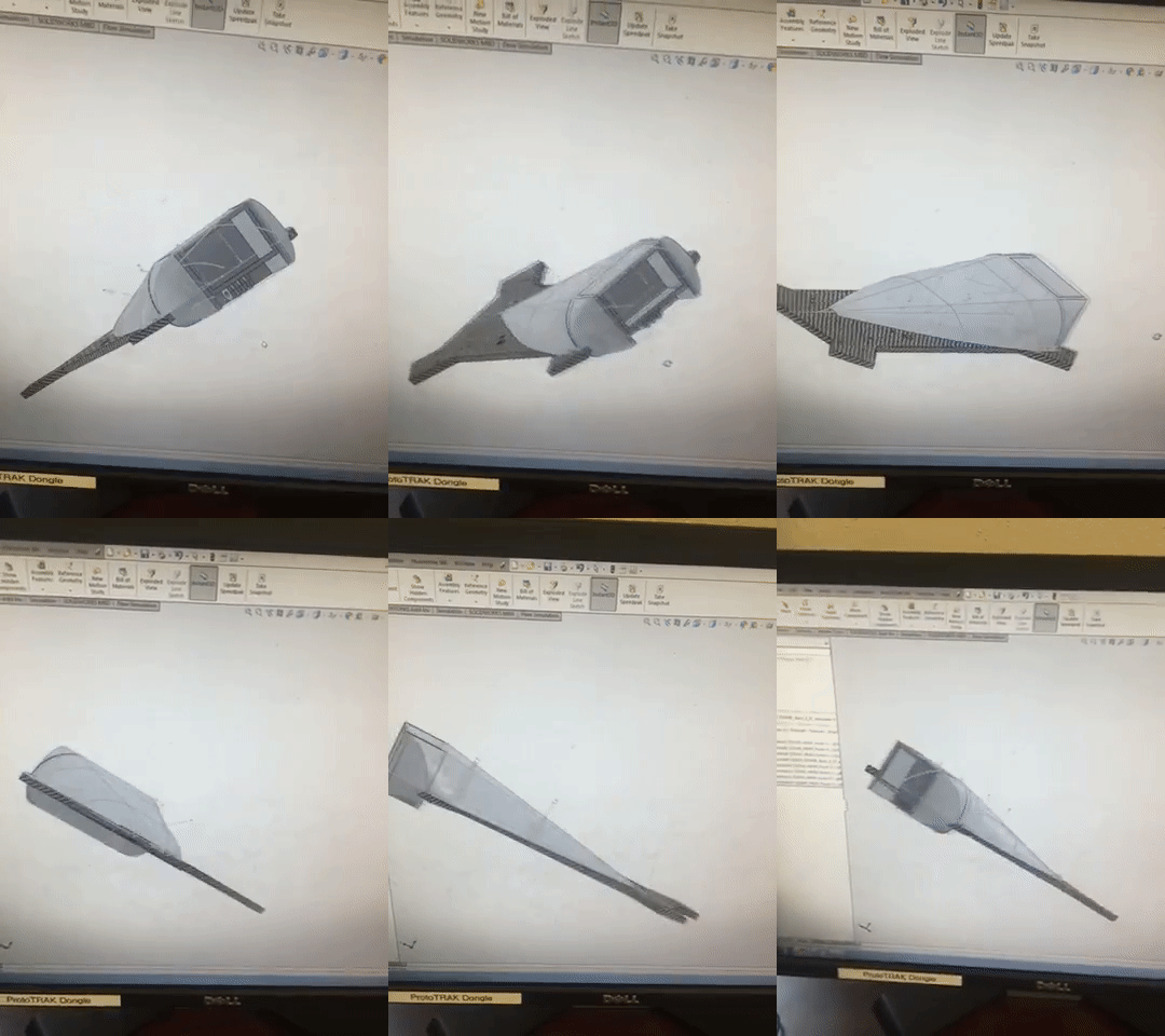
A potential canopy to cover the electronics. Included in the design is an actioncam mount.
Canopy
One feature I included in later designs of the quad included being able to withstand rain. Typically rain prevents most of these aircraft from flying as the bodies of the drones allow moisture to seep into the processors and ESCs. Considering that brushless motors can stand up to water, housing the electronics within a canopy could prevent light rain from forcing a landing.
Telescoping Rod
Having just purchased a Gear 360 actioncam, I would like to suspend it like I would have the other camera I built. However, with its light weight, it would be interesting to test how a telescoping rod might work in addition to this, potentially with an actuator to flip it down much like a retractable leg. Doing so might make for a more interesting shot, especially when it is important to keep the drone farter away from what it is filming.